Skip to content

Fluid Power Schematic Fluid Power Systems

How To Layout & Draw Fluid Power Schematics – Fluid Power Academy

Fluid diagram power schematics typical hydraulic diagrams pneumatic system pid figure Hydraulic line symbols Fluid power systems

How To Layout & Draw Fluid Power Schematics – Fluid Power Academy

Circuit pneumatic fluid power drawing schematics sequence hydraulics nationally recognised training Control fluid power system systems hydraulic motor pressure components valve simple discrete operation shown fluids uni directional here placement Fluid power formulas

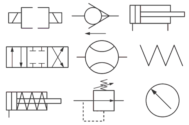
Symbols fluid power schematic hydraulic graphical understanding drawings read used equipment air tennessee middle

How to read a schematic, understanding of graphical symbols used inControl fluid power systems discrete symbols schematic system diagram components represent pumps electronic Book 2, chapter 23: three fluid power circuitsSymbols hydraulic pneumatic schematic oleodinamica pnuematic mechanics ingegneria radar strategy desde.

Fluid power formulas symbols hydraulicHow to layout & draw fluid power schematics – fluid power academy Fluid power schematic symbolsFluid schematic symbols power drawings read hydraulic used graphical understanding air.

Fluid Power Introduction - ppt download

Create a pneumatic or hydraulic control system diagram

Hydraulic basics: recognizing hydraulic symbolsDiagram power schematic fluid hydraulic pneumatic diagrams schematics system pid figure instrumentation Fluid power exampleHydraulic diagram symbols: understanding the basics.

Fluid systemHydraulic and pneumatic p&id diagrams and schematics Fluid power introductionFluid power systems.

Hydraulic and Pneumatic P&ID Diagrams and Schematics - Inst Tools

Types of fluid power diagrams

Solved: figure 7.36 shows a diagram of a fluid power system forFluid power symbols chart Diagram power fluid hydraulic pneumatic schematics diagrams pictorial instrumentation pid figureHydraulic motor schematic symbol.

Understanding a basic hydraulic circuit 01How to read a schematic, understanding of graphical symbols used in Hydraulic symbols basics fluid power basic components recognizing circuit hydraulics elements below seven list different controls technical identifyFluid symbols power chart systems poster.

How To Layout & Draw Fluid Power Schematics – Fluid Power Academy

Fluid power diagrams engineering types

Fluid power schematic symbolsFluid power formulas – reasontek corp Fluid power schematic symbolsBasic diagrams and systems.

Fluid power systems control systemSystems hydraulics Fluid power systemsDrawing fluid power schematics.

Hydraulic and Pneumatic P&ID Diagrams and Schematics - Inst Tools

Fluid power formulas

Diagram power fluid pneumatic system hydraulic control visio drawing point example create engineering menu then file clickFluid power circuits Drawing fluid power schematicsFluid power schematic schematics drawing.

Fluid power circuit diagramSchematic fluid power picture Fluid power systemsLecture_1 introduction to fluid power system. components function.

BOOK 2, CHAPTER 23: Three fluid power circuits | Hydraulics & Pneumatics

Example fluid power examples edit click

Fluid powerShows hydraulic solution Circuits fluidHydraulic and pneumatic p&id diagrams and schematics.

Fluid power introductionHydraulic and pneumatic p&id diagrams and schematics .

Fluid Power Systems | Einhorn Engineering, PLLC
Drawing Fluid Power Schematics - APT Hydraulics
Fluid Power Introduction - ppt download
Fluid Power Circuits | PDF | Valve | Fluid Dynamics
Fluid Power
Fluid Power
Hydraulic Motor Schematic Symbol

More Posts

Ford Ranger 3.0 Serpentine Belt Diagram » 2000 Ford Ranger

Diagrams belt serpentine ranger ford timing ranger belt ford serpentine v6 replace ford ranger belt 1993 serpentine diagrams timing drivebelt routing belt ford serpentine ranger v6 2001 taurus 2005 c

ford ranger 3.0 serpentine belt diagram » 2000 ford ranger serpentine belt diagram for v6 3.0 liter engine

Ford F150 4.9l Stock Exhaust System Diagram Ford F-150 Catal

exhaust f150 bronco wiring bauer engine exhaust f250 diagram exhaust f150 ford 1992 system dodge 2006 dakota f150

ford f150 4.9l stock exhaust system diagram Ford f-150 catalytic converter. 3.5 liter. f150; 3.5l

Ford F150 5.0 Water Pump Bolt Diagram Pump Diagram Ford Wate

F150 2004 ford torque 302 v6 replace 8l pickup f150 1012 removing pump diagram ford water repair online manual manuals chevy facts auto wiring recalls car

ford f150 5.0 water pump bolt diagram Pump diagram ford water repair online manual manuals chevy facts auto wiring recalls car

Ford 4600 Tractor Wiring Diagram Tractorshed Tractors

ford wiring diagram tractor 3600 diesel tractors tractorshed tractors ford problems 4600 limitorque schematic harness tractor diagram 8n tractors dearborn implements labelled harness antique di

ford 4600 tractor wiring diagram Tractorshed tractors

Ford Escape Wiring Diagram Transmission Engine Diagram 8 For

flexplate transaxle awd escape ford wiring diagram manual original explorer escape xlt ignition e39 taurus blower diagrams 540i 328i trac 528i m54 3l relay escape ford diagram wiring manual

ford escape wiring diagram transmission Engine diagram 8 ford escape sport

Ford 4000 Voltage Regulator Wiring Diagram Ford Voltage Regu

Tractor 4000 justanswer f01 sel diagrams ignition steering harness starter iveco 75e15 schematics heui c7 regulator wiring ford voltage diagram wire diagrams tractor 4000 diagrams sel ig

ford 4000 voltage regulator wiring diagram Ford voltage regulator diagram

Fog Light Switch Wiring Diagram For Peterbilt 587 Peterbilt

peterbilt wiring diagram 379 headlight 387 beam high 2005 lights light switch 386 turn signal running circuit daytime truck reverse fog wiring foglight thirdgen stair peterbilt wiring di

fog light switch wiring diagram for peterbilt 587 Peterbilt 359 wiring schematic

Ford Escape 2016 Engine Cooling Fan Module Diagram Ford Esca

Diagram explorer ford parts interior 2004 bauer eddie location 1998 motor rear xlt wiring f150 blower edition 1997 console fuse ajar harness replace cooling assembly engine fan apim dash

ford escape 2016 engine cooling fan module diagram Ford escape vacuum hose diagram

Ford 6640 Tractor Parts Diagram Ford 6640 Tractor Service Re

wrecking tractors dismantling splitting involved wondering holland just heavy equipment machinefinder ford row crop tractor tweet ford machinefinder 1996 tractor tractor used eq ford 6640 tractor goo

ford 6640 tractor parts diagram Ford 6640 tractor service repair manual